Thursday, 21 June 2012

Rack Planner Update


Once again, not a massive amount to see that's new on the interface, but the code has grown from 300 to 600 lines today. It's alot more robust now. New functions for today:
  • Save - the output is called rack.xml. It conforms to the expected structure so loads successfully into dougcl's planner
  • Load - re-reads in the rack.xml file. I haven't tried loading in a dougcl-planner-created file yet, but it should work.
  • Delete module - richt-clicking on a module now deletes it
  • 3 new code functions to better manange the rack array.
  • Debug mode on/off
 Here's a picture of it loaded with what's in one of my LC9 cases:


Rack Planner Update


Lots of code that doesn't seem to have much of a visual impact today, but that keeps the modules confined in the racks correctly. One new feature worth mentioning are the 'HP Rulers' that appear as you drag modules around. These indicate the space available either side of the module and allow for easy positioning without having to count the dots/keyboard taps (see image above where an Echophon is being positioned 8HP from the right side of the case).

Tuesday, 19 June 2012

RichyHo's Rack Planner


We all love our rack planner of choice don't we? Well I'm going to use that love to craft my own. I'm using Processing to code it and basing it heavily on dougcl's Rack Planner (I spoke to him today to make sure I've got his blessing, and I have :-). This is my "let's learn Processing" project and in the last 24 hours it's taught me so much, including how to....
  • Unzip files (that's the module zips)
  • Read text files (the module.xml files)
  • String manipulation
  • Mouse handling
  • Image scaling
  • Snap to a grid
  • Handle fonts
  • Manage arrays
It uses the existing module zip files as so much effort has already gone into creating these it would be crazy to reinvent this particular wheel. The feature list so far (with a LONG way to go) is....
  • Browse a 'modules' subfolder to pick a module to add
  • Preview the module's "drop zone" (see green in image above)
  • Check it's not being dropped on top of another module (override will be available)
  • Pick up and move a module to a new unoccupied location
  • Define a rack structure (width, rows, columns, scaling)
  • Track HP usage
Next steps...
  • Delete module
  • Save & load standard Rack Planner files
I want to bring together the best bits from dougcl's Rack Planner, the online Modular Planner and also the Eurorack Database and add many new features of my own. I love it when a new project gets a grip on me!

Comments, ideas and any other feedback would be welcomed.

Saturday, 2 June 2012

Arduino, Processing & The Modular (Part 5)

A code update on the Arduino side sees not just CV values being sent to the serial (USB) port but also the values from the randomness knob so that these can be displayed on the Processing app's screen. These values are prefixed with an 'R' before sending so that they can be detected and treated differently when they are received. Turning the randomness kob now changes a value and moves a green bar on the app as shown below:


Ultimately all control values will be sent when they change (and also upon receipt of an "I'm starting" message sent the other way down the wire by the app to the Arduino. That way initial values will show when the app starts rather than having to wait for a knob to be turned for them to be updated to the current true values.

Friday, 1 June 2012

Arduino, Processing & The Modular (Part 4)


Today's arduino code changes include adding support for the left hand pot. This now sets the amount of randomness. Fully CCW = none (steady CV out). Fully CW = totally random. The Right green LED now indicates when double-clocking (2x tempo) randomly occurs. The picture below shows the output resulting from this knob being turned from zero to full over the course of the screen sweep.


Processing code changes include a test to represent the incoming data with a circular rather than linear sweep. It's not particularly inspiring and was only tried in the spirit of "let's see what happens"

Thursday, 31 May 2012

Arduino, Processing & The Modular (Part 3)

So now we have hardware which sends out a clock pulse and a random voltage. Well, I say 'random', but it's now more of a varying voltage. At any point it can go up or down from its current value by a limited amount. If the values go above the mximum they revert to 0 and go on from there. If they fall below 0 they go to the max value and go on from there. This can all be visualized at pretty close to real time in various ways using Processing code running on the PC to which the Arduino is connected by USB.


Processing watched for an incoming serial stream and plots the points with x being time and y being voltage.

Arduino, Processing & The Modular (Part 2)

Once the final stage of adding a potentiometer to control the clock rate had been proved to work I set about rigging up a simple aluminium faceplate to hold the jack sockets, LEDs and potentiometer in place. I added an extra pot, LED and socket for future use. The knob next to the red LED changes the clock rate. The other 2 knobs are unused. Soldering the Arduino's 'tipped' patch leads to the front panel components allowed for easy subsequent repatching on the breadboard.


Arduino, Processing & The Modular (Part 1)

My next experiment is a hardware and software combo. An Arduino Leonardo microcontroller (which I was lucky enough to win last week in a competition run by the fantastic Arduino store oomlout.co.uk) programmed and hooked-up to talk to my modular synth and also to the computer. The first stage involved getting to grips with the Arduino's PWM analog output. This was unusable for control voltage generation as it's really buzzy. It needed filtering so I experimented with a simple RC filter circuit on the breadboard and found a resistor/capacitor combination that works pretty well (further work needed as it slews quite alot - I'm running it through the modulars sample & hold module to reduce that further.). Next came a visual indication of the random output voltage by means of a green LED. Then a clock output visualized with a red LED was added.


With each clock pulse the Arduino's code sends the text value of the random voltage out via USB to the PC to allow it to be picked-up by a Processing application that's watching for this data stream.

Thursday, 19 April 2012

Doepfer LC9 Extension Box for Theremin Module


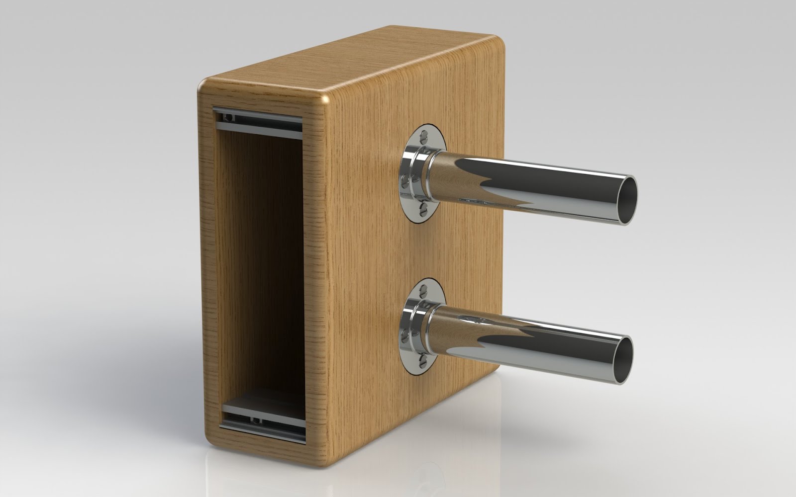
8HP extension box for Doepfer LC9 case to allow for positioning of Doefper A-178 Theremin (or other) modules outside of the main enclosure. Power to run through lower metal cylinder via a longer than normal ribbon cable.

Friday, 2 July 2010